How an Ebike Controller, Battery and Motor Must Match
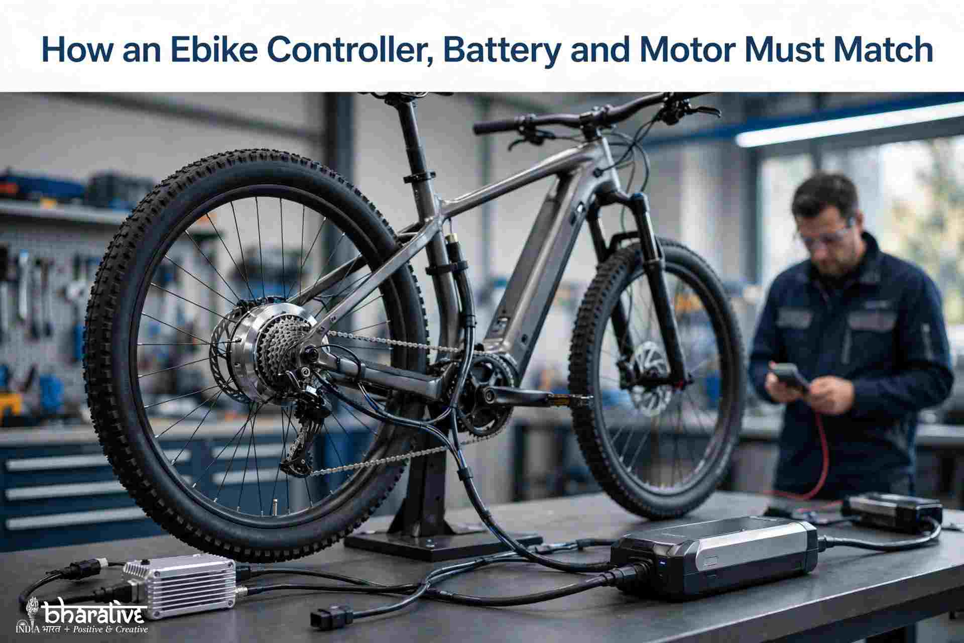
Replacing an electric bike controller can seem straightforward. The connectors appear to fit, the display switches on, and the wiring looks compatible. Yet the motor may stutter, acceleration may become inconsistent, or the bike may suddenly lose power when climbing a hill.
These problems often happen because the battery, controller and motor have not been matched correctly.
An electric bike’s power system works as a connected unit. The battery supplies electrical energy, the controller regulates how that energy reaches the motor, and the motor converts it into movement. Each component has electrical and thermal limits that must be respected.
Choosing a controller based only on its connectors or advertised wattage is not enough. Voltage, battery current, phase current, motor temperature, wiring capacity and communication compatibility all matter.
The most important rule is to match voltage first, then establish safe current limits. The battery’s continuous discharge capability, the controller’s output settings and the motor’s sustainable thermal capacity must work together. Acceleration and other ride characteristics should only be adjusted after these fundamental limits are established.
What an Ebike Controller Actually Controls
An ebike controller is often described as the system’s brain. A more practical way to understand it is as a power-management and communication unit.
It receives low-power signals from components such as the throttle, pedal-assist sensor and brake switches. It then controls the electrical power delivered to the motor by coordinating the timing and current of the motor phases.
Depending on the system, the controller also manages:
- Motor phase timing and current
- Battery-side current demand
- Throttle response
- Pedal-assist operation
- Brake cut-off signals
- Motor Hall sensor information
- Display communication
- Low-voltage and other protection functions
A controller must therefore match more than the battery voltage. It also needs compatible motor phases, sensor connections, display communication and input wiring.
A display that powers up does not prove that the controller is compatible with the rest of the bike. Before buying a replacement, check the wiring diagram, connector pinout, supported display protocol and motor sensor requirements.
Match Voltage Before You Match Motor Wattage
Battery voltage is the first electrical specification to check when selecting an ebike controller.
A battery’s nominal voltage is not the same as its voltage immediately after charging. For example, a typical 52V lithium-ion battery pack reaches approximately 58.8V when fully charged. The controller must be rated to handle that maximum voltage, not just the nominal figure printed on the battery.
A controller with an insufficient voltage rating may be damaged even if the battery’s nominal voltage appears close to the controller’s advertised specification.
A lower-voltage mismatch can cause different problems. For example, a 36V battery connected to a controller configured for a 48V system may trigger low-voltage protection or prevent the motor from operating correctly.
Reducing the controller’s current setting through an app does not solve an unsupported voltage mismatch. Current limits and voltage ratings are separate electrical considerations.
Before installation, confirm:
- Battery nominal voltage
- Battery full-charge voltage
- Controller supported input-voltage range
- Controller low-voltage protection settings
- Display voltage compatibility
- Any manufacturer-specific voltage requirements
Voltage compatibility should be established before considering motor wattage or performance settings.
Battery Current, Phase Current and Motor Watts Are Different
Controller advertisements sometimes show an amp rating without clearly explaining what it represents. This can lead buyers to compare controller current directly with the wattage printed on a motor.
These figures describe different things.
| Electrical figure | What it measures | Why it matters |
|---|---|---|
| Battery or DC current | Current drawn from the battery | Determines the electrical load on the battery cells, BMS, connectors and main wiring |
| Motor phase current | Current circulating through the motor windings | Influences motor torque and heat, particularly during low-speed operation |
| Motor wattage | A nominal motor power rating | Provides a general rating but does not independently determine the correct controller current |
A simple calculation using voltage multiplied by battery current estimates battery-side electrical input power. It is useful when comparing controller settings, but it is not the same as mechanical power delivered at the wheel.
Actual output is affected by electrical and mechanical losses, operating conditions and motor efficiency.
A programmable controller with a relatively high maximum current may be suitable for different motor applications when its settings can be adjusted appropriately. However, a lower setting does not automatically make every controller compatible with every battery or motor.
The controller’s voltage rating, wiring, connectors, sensor support and motor thermal limits must still be suitable.
Framework A: The Three-Ceiling Rule
A practical way to approach controller selection is to identify three important continuous operating limits before choosing a current setting.
The safe continuous operating current must stay within the lowest applicable limit, while the wiring and connectors provide additional boundaries.
1. Battery Ceiling
The battery ceiling depends on the battery cells and the battery management system (BMS).
The BMS monitors and protects the battery pack against operating conditions such as excessive current and voltage. Battery listings may advertise both continuous and peak discharge ratings, but these figures should not be treated as interchangeable.
For sustained riding, use the verified continuous discharge capability rather than relying on a short-duration peak figure.
2. Controller Ceiling
The controller ceiling is determined by its maximum battery current and the settings available to the user.
A controller advertised as 60A may support a lower operating current through its programming options. However, percentage settings should not automatically be assumed to translate directly into the same percentage of actual current. Check the manufacturer’s documentation or measure the configured limit where necessary.
3. Motor Ceiling
The motor ceiling is its ability to handle heat during sustained operation.
Motor temperature depends on several factors, including:
- Motor design and winding
- Wheel size
- Rider and cargo weight
- Road gradient
- Riding speed
- Cooling conditions
- Duration of high-load operation
A motor may tolerate a brief power increase but overheat during a long climb if the current remains too high.
Wiring and Connector Limits
The battery, controller and motor are not the only components that need protection. Cables, terminals and connectors must also be rated for the current they carry.
A system can have a suitable battery and controller but still develop dangerous heat at an undersized connector or poorly installed cable.
For this reason, the three-ceiling rule should always be applied alongside a wiring and connector inspection.
Example: A 40A BMS and a 60A Controller
A battery with a verified 40A continuous BMS rating may be paired with a controller capable of 60A only if the controller can be reliably configured below the battery’s permitted continuous current.
The motor and wiring must also support the selected operating conditions.
If the controller is left unrestricted at 60A, it can exceed the battery’s continuous discharge capability and cause the BMS to intervene.
The BMS should be treated as a protection boundary, not as a normal riding control. Repeated BMS cut-outs during ordinary riding indicate that the system needs investigation and its settings or component specifications may be unsuitable.
Framework B: Symptom, Cause and Operating Limit
When an ebike behaves unexpectedly after a controller replacement, the symptoms can help identify which compatibility issue needs investigation.
| Symptom | Possible cause | Area to investigate |
|---|---|---|
| Motor stutters or fails self-learning | Hall sensor and phase mismatch or unsupported sensor protocol | Motor and controller compatibility |
| Power cuts out during climbs | Controller demand exceeds battery or BMS capability | Battery current limit |
| Motor becomes excessively hot | Sustained load exceeds the motor’s thermal capacity | Motor operating limit |
| Display powers up but system will not run | Incorrect voltage configuration or protection setting | Voltage compatibility |
| Strong initial acceleration followed by shutdown | Excessive current demand or overheating | Controller, battery and wiring |
| Connectors become hot or melt | Underrated wiring, poor connections or excessive current | Wiring and connector rating |
These symptoms are diagnostic clues rather than definitive proof of a particular fault. Check the manufacturer’s wiring information, error codes and electrical specifications before replacing components.
Why FOC Sine-Wave Control Changes Ride Quality
Field-oriented control (FOC) is a motor-control method that manages motor phase currents in relation to rotor position.
Instead of relying on less refined switching behaviour, FOC aims to control the motor’s magnetic field more smoothly. This can result in quieter operation, more predictable torque delivery and a more controlled riding experience.
Ride quality matters in different ways depending on how an ebike is used.
A commuter may prefer gentle power engagement when accelerating on a wet road. A rider tackling technical climbs may want a more responsive but predictable delivery of torque.
Hall sensors normally provide information about the rotor’s position. Some controllers also support Hall-free operation or self-learning functions that help identify compatible motor phase and sensor relationships.
However, self-learning is not universal. It does not guarantee compatibility with proprietary mid-drive systems or unusual sensor arrangements.
What the Ride Power App Adds
A programmable controller can offer additional control over how an ebike responds to rider input.
The Bluetooth-programmable ebike controllers described by Ride Power are designed to connect with the Ride Power app on iOS and Android. The source describes live system readings and adjustable controller parameters, supported by installation and tuning experience.
The main benefit of this type of programming is not simply the ability to increase power. It is the opportunity to configure current limits, acceleration behaviour and other supported settings more deliberately.
Before relying on an app for system configuration, confirm that the controller model, Bluetooth module, phone operating system and app version are compatible.
An app can help adjust a correctly selected controller, but it cannot change the controller’s physical voltage rating or make an unsuitable connector safe.
Tune Current Before Acceleration
It can be tempting to increase acceleration strength as soon as a new controller is installed. However, a safer approach is to establish the electrical limits first.
A sensible tuning sequence is:
- Save or export the original controller parameters before making changes.
- Confirm the battery voltage and the controller’s supported input range.
- Set battery-side current within the verified BMS and battery-cell limits, while considering the motor’s sustainable load.
- Check low-voltage protection and the relevant voltage settings.
- Run the self-learning procedure if the controller requires it, then verify smooth and correct forward rotation.
- Begin with a moderate acceleration-strength setting.
- Configure PAS1–PAS5 for clearly defined riding situations, if supported.
- Test regenerative braking and any limit modes only after normal operation is stable.
The first powered test should be performed with the driven wheel safely raised and the bike secured. Keep a safe way to disconnect power and follow the controller manufacturer’s installation instructions.
Do not touch moving components or attempt adjustments while the wheel is operating.
The goal is dependable performance under realistic riding conditions. A moderate setting that can sustain a long climb is more useful than an aggressive launch that causes overheating or repeated shutdowns.
Regenerative Braking Is a System Feature
Regenerative braking allows a compatible motor to act as a generator during deceleration, sending some electrical energy back toward the battery.
On suitable direct-drive hub motors, regenerative braking can provide controlled deceleration and may reduce wear on the mechanical braking system.
However, regeneration requires several components to work together:
- The motor must support generation through the wheel.
- The controller must support regenerative braking.
- The battery and BMS must accept the incoming charge current.
- The brake input must activate the controller’s regenerative-braking function.
- The system must manage charging safely when the battery is near full capacity.
A nearly full battery has limited room to accept additional energy. The controller and battery protection system must therefore handle regenerative current appropriately.
Regenerative braking should not be treated as guaranteed extra range. The amount of recovered energy depends on terrain, speed, riding conditions and battery state.
Geared hub motors with an internal freewheel generally cannot provide conventional regenerative braking because the wheel can rotate without driving the motor.
BMS Matching Starts with Continuous Current
Battery capacity and battery discharge capability answer different questions.
Capacity, usually expressed in amp-hours (Ah) or watt-hours (Wh), indicates how much energy the battery can store. It helps estimate potential riding range.
Continuous discharge current indicates how much current the battery can supply under its specified operating conditions.
When comparing ebike batteries for conversion kits, check the following specifications together:
- Nominal and full-charge voltage
- BMS continuous discharge rating
- Battery-cell discharge capability
- Peak discharge rating and its permitted duration
- Connector type and current rating
- Cable size and installation requirements
- Physical dimensions and mounting compatibility
A higher-capacity battery is not automatically capable of supplying more current. Likewise, a battery with a high advertised peak rating may not be suitable for continuous high-load riding.
A programmable controller may allow a higher-rated controller to operate with a lower-current battery, provided the current limit is configured correctly and the controller’s settings are verified. Never rely on an assumed app percentage without checking how that setting translates into actual battery current.
Fully Potted Does Not Mean Maintenance-Free
Some ebike controllers use resin potting to protect their internal circuit boards.
A fully potted design can help protect electronic components against moisture, vibration and road impact. Thermally conductive potting compounds may also help transfer heat from internal components toward the controller case.
This can be useful on electric bikes exposed to road conditions and vibration.
However, potting does not make the entire controller assembly waterproof or eliminate maintenance requirements.
Connectors, cable exits, damaged insulation and exposed wiring can still allow moisture to enter. The controller case also needs an appropriate path to release heat.
For better protection:
- Keep connectors away from direct tyre spray where possible.
- Avoid cable arrangements that create low points where water can collect.
- Inspect cable insulation and connector housings regularly.
- Provide suitable strain relief for cables.
- Keep the controller’s heat-dissipation surfaces unobstructed.
- Do not wrap the controller in insulating material that could restrict cooling.
The protection offered by potting should be considered alongside the enclosure rating and the condition of the complete installation.
UK Limit Modes Need Careful Legal Language
Some programmable ebike systems provide different power and speed modes.
The Ride Power system described in the source offers three limited modes and an unlimited mode. Its Limited 1 setting is described as applying a 250W and 25km/h configuration to throttle and pedal assistance, while stricter settings may disable the throttle or reduce its operation to walk-assist speed.
These settings can change how a controller behaves, but selecting a limited mode does not automatically certify an electric bike as road legal.
In the UK, the legal classification of an electrically assisted pedal cycle depends on the complete vehicle and the applicable requirements. These include factors such as continuous rated motor power, assistance speed, pedal-assistance operation and the vehicle’s accessible operating modes.
Owners should check the latest official UK requirements and confirm that the complete bike complies in every mode available for use on public roads.
A controller setting is not a substitute for legal compliance.
Buying and Installation Checklist
Before purchasing a replacement controller, and again before the first ride, work through this checklist.
- Confirm the battery’s nominal voltage and full-charge voltage.
- Check the BMS continuous discharge current rather than relying on peak current alone.
- Identify the controller’s maximum battery current and available phase-current settings.
- Confirm the motor type, winding and Hall sensor arrangement.
- Check the motor’s sustainable thermal capacity.
- Verify display voltage and communication compatibility.
- Confirm throttle, PAS and brake cut-off pinouts.
- Check light, alarm and other auxiliary connections where applicable.
- Verify battery connector polarity, cable gauge and current rating.
- Check the controller’s physical dimensions and mounting position.
- Confirm that the controller has an appropriate heat-dissipation path.
- Verify self-learning or Hall-free support for the intended motor.
- Confirm that the motor, controller, battery and BMS all support regenerative braking before enabling it.
- Check Bluetooth module and app compatibility.
- Inspect waterproofing, connector placement and cable strain relief.
A controller should not be ordered simply because its plugs appear similar to the original unit. Electrical specifications and communication compatibility must be confirmed first.
Frequently Asked Questions
What amp controller do I need for a 1000W ebike motor?
There is no universal controller current for every 1000W motor.
For example, dividing 1000W by 48V gives approximately 20.8A of idealised battery-side current. However, this calculation does not account for electrical losses, acceleration demand, operating conditions or the motor’s thermal limits.
The correct controller setting depends on the battery’s continuous discharge capability, controller specifications, motor capacity and wiring. Use the three-ceiling rule rather than choosing a controller from motor wattage alone.
Can I use a 60A controller with a 40A BMS?
It may be possible if the controller supports a reliable battery-current limit below the battery’s verified 40A continuous rating.
The motor and wiring must also support the selected operating conditions. An unrestricted 60A setting can exceed the battery’s continuous discharge capability and trigger BMS protection.
Can the app make a large controller safe for a smaller motor?
An app may allow users to reduce battery current and soften acceleration, which can help configure a suitable system.
However, software settings cannot change the controller’s voltage rating, correct an incompatible connector or increase a motor’s thermal capacity. Programming can help establish safe operating limits, but it cannot make an fundamentally incompatible combination suitable.
Does a higher-amp controller make an ebike faster?
A higher current limit can increase available torque and acceleration when the motor and battery can use the additional current safely.
It does not automatically increase the bike’s maximum speed. Top speed also depends on battery voltage, motor winding, wheel size, operating conditions and controller settings.
Does self-learning work with every ebike motor?
No. Self-learning is designed to identify phase and Hall sensor relationships for many compatible brushless motors.
It does not guarantee compatibility with every motor, particularly proprietary mid-drive systems or motors using unusual sensor arrangements and communication protocols.
Check the controller manufacturer’s compatibility information before relying on self-learning.
Does regenerative braking work with a geared hub motor?
Usually not with conventional geared hub motors.
Many geared hub motors contain an internal freewheel mechanism that allows the wheel to rotate without driving the motor backward. Direct-drive hub motors are generally better suited to regenerative braking.
Is a fully potted controller waterproof?
Not necessarily. Potting can provide strong protection for internal circuit boards against moisture and vibration, but external connectors, cable exits and damaged insulation remain vulnerable.
The controller also needs an appropriate thermal path. Check the manufacturer’s stated protection rating rather than assuming that resin potting makes the complete assembly waterproof.
Can Limit Mode make a high-power kit UK road legal?
Not automatically. A limit mode can change power and speed behaviour, but UK road legality depends on the complete vehicle and all accessible operating modes.
Check current official requirements and confirm that the bike meets the relevant rules before using it on public roads.
Match the Limits Before You Tune the Ride
An ebike controller should never be selected in isolation. Start by checking battery voltage, BMS continuous current and the motor’s sustainable thermal capacity. Then confirm phase wiring, Hall sensors, display communication, throttle, PAS and brake compatibility.
The battery, controller, motor and wiring must operate within their respective limits. Only after these requirements are satisfied should acceleration strength, pedal-assist levels, regenerative braking and other performance settings be adjusted.
The most suitable controller is not necessarily the one with the highest advertised amp rating. It is the one that works reliably with the battery, motor and supporting components under real riding conditions.
Matching the system correctly is the foundation of dependable performance, better ride quality and a safer electric bike conversion.
You may also like ...